Create DRR
This tool is used to create DRR (Digital Reconstruction Radiographs) utilizing the 3D volume (usually a CT or MR scan). 3D landmark annotations for the 3D volume are required to create the DRR (to determine the initial volume orientation). The output projections are saved as HDF5 files but projected DRR images can also be saved as PNG files in the output directory.
Components
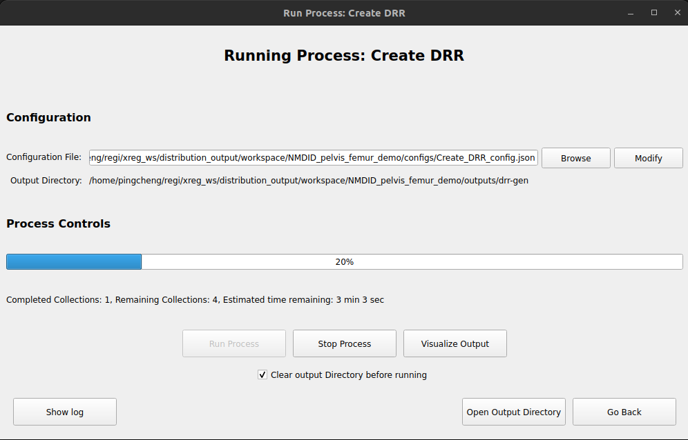
For the main window, we only need to sepcify the configuration file
Configuration File: The configuration JSON file for the DRR creation. By default, this paths for configs files are located at <workspace_dir>/configs. Note that the process name for the JSON fils should be Create DRR.
Process Controls: Run the DRR creation process.
Generating a DRR Generation Configuration File

The configuration file is a JSON file that contains the following information:
Volume(.nii/.nii.gz): The 3D volume to be used for the DRR creation.
3D Landmarks(.fcsv): The 3D landmark annotations for the 3D volume.
Landmark file to be projected (Optional): The 3D landmark annotations for the 3D volume to be projected. This can be the same as the 3D landmarks file (which means that all the landmarks will be projected and annotated in the DRR images) or a different fcsv file.
Experiment Name: The name of the experiment mainly to determine the output directory. The defualt output directory will be <workspace_dir>/outputs/<experiment_name>.
Anatomies: Specify the list of anatomies and the landmark names in this table. The landmark names have to be identical to the landmark names used in the 3D landmarks file. The specified center landmark label will be used as the center of anatomy rotation during the DRR creation. The model path (.stl) for the anatomy can be specified but is optional.
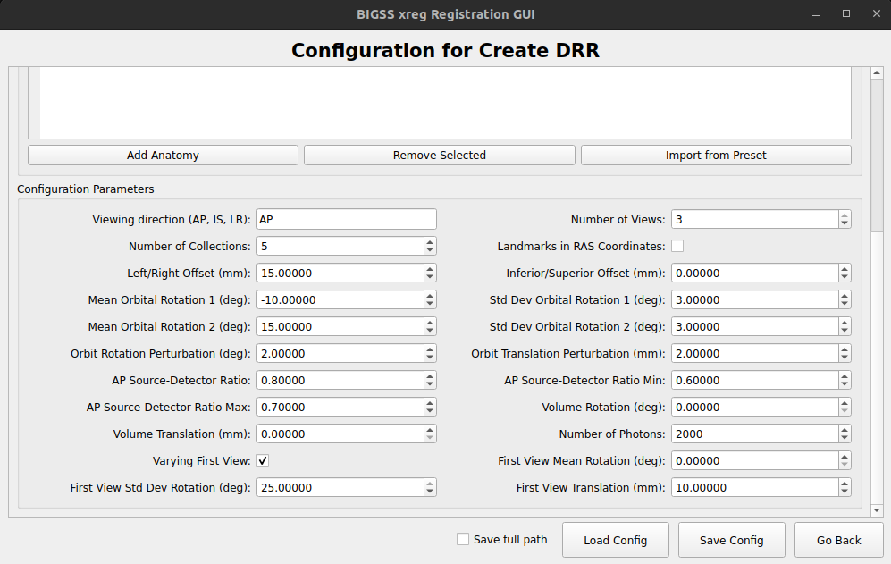
- Configuration Parameters:
Viewing Direction: The viewing direction for the DRR creation. AP stands for Anterior-Posterior, LR stands for Left-Right, and IS stands for Inferior-Superior.
Number of Views: The number of views to be created for each collection of image. Currently the software supports 1 or 3 (multi-view) views.
Number of Collections: The number of collections of images to be created. A total of Number of Collections * Number of Views DRR images will be created.
Left/Right Offset: The offset for the left and right view. The offset is applied to bring more of the target anatomy into view. (Left is positive).
Inferior/Superior Offset: The offset for the inferior and superior view. The offset is applied to bring more of the target anatomy into view. (Superior is positive).
Mean Orbital Rotation for view X: The mean rotation angle for the view X.
Std Dev Orbital Rotation for view X: The standard deviation of the rotation angle for the view X.
Orbit Rotation Perturbation for view X: The amount of non-orbital rotation applied to the view X.
Orbit Translation Perturbation for view X: The amount of translation perturbation applied to the view X.
AP Source-Detector Ratio: The positioning parameter along the source-to-detector direction for first view. The value has to be between 0 and 1. The closer to 0, the closer to the camera. The default value is 0.6.
Volume Rotation: Apply random rotation applied to the initial pose of the volume in degrees. This should only be used if the goal is to create a more diverse pose simulation of the projection (like for DL training dataset creation)
Volume Translation: Apply random translation applied to the initial pose of the volume in mm.
Number of Photons: The number of photons used when adding Poisson noise. The default value is 2000.
Varying First View: Set to True if the first view is varied. This is used to create a more diverse pose simulation of the projection.
First View Mean Rotation: The mean rotation angle for between the first views across different collections.
First View Std Dev Rotation: The standard deviation of the rotation angle for between the first views across different collections.
First View Translation: The amount of translation applied to the first view across different collections.
How to use
Once the configuration file is generated, the user can run the DRR creation process by clicking the "Run Process" button. Note that the DRR generation process can take a while to complete.
To mointor the generation process, the "Visualize Output" window will display any generated DRR images in real-time.
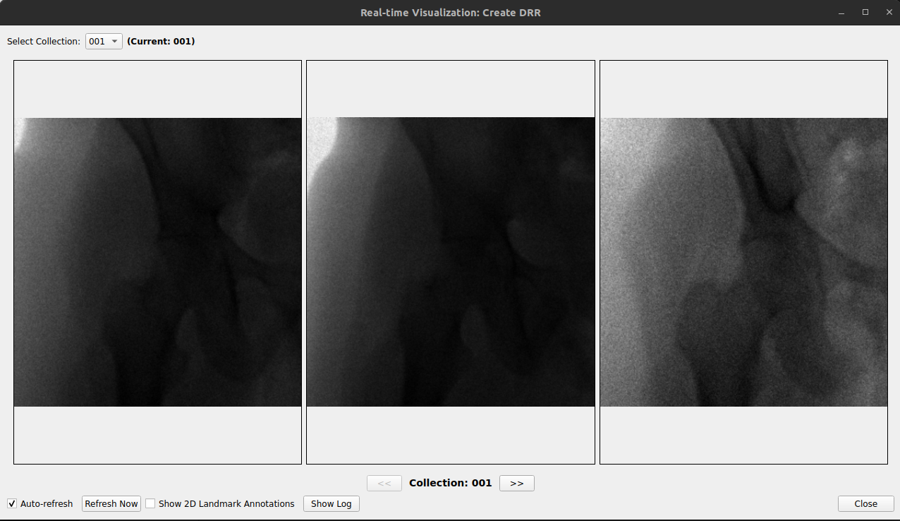
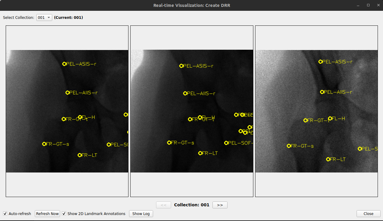
The annotated DRR images can also be visualized in real time, as shown in the figure below.
Troubleshooting
If the DRR generation process is not working, the user can check the terminal outputs for any error messages.
Contact BIGSS team for support with the error messages if the issue persists.